
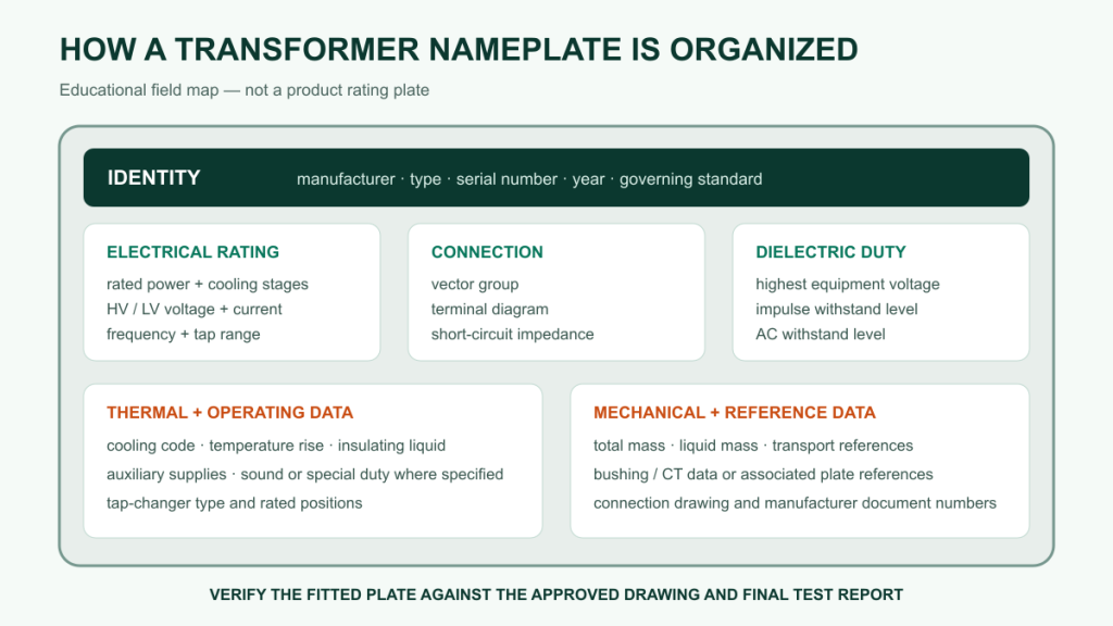
A transformer nameplate is the operating identity of one manufactured unit. It connects the approved design, terminal arrangement, protection settings, test report and site operating limits. Buyers should read the values as a coordinated set rather than treating voltage, kVA or vector group as isolated catalog fields.
Start with identity and rating basis
Record the manufacturer, serial number, year, governing standard and transformer type before comparing electrical values. The serial number should link the physical unit to its routine test report and final document dossier. Also check whether the unit is a two-winding transformer, autotransformer, three-winding transformer or another defined arrangement; the same voltage figures can represent different system duties.
Rated power and cooling stages
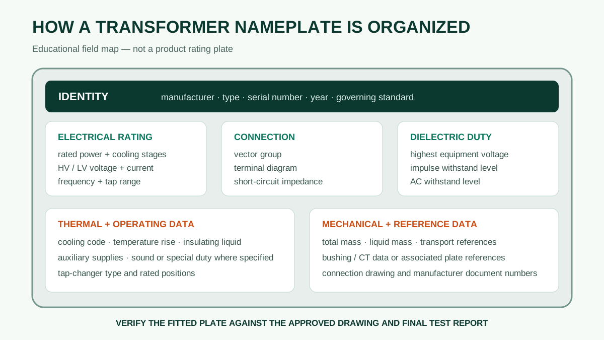
Rated power may be stated as one value or as several values linked to cooling stages, such as ONAN and ONAF. A marking such as 40/50 MVA does not mean that 50 MVA is continuously available under every condition. Confirm which cooling equipment must operate, the specified ambient and temperature-rise basis, and whether auxiliary supply is available and reliable.
Three-winding units and autotransformers require particular care because each winding can have its own rated power or loading limitation. Do not infer individual winding capability from a single headline MVA value.
Rated voltage, frequency and tapping data
Read high-voltage and low-voltage ratings together with system frequency and tap information. A plate may show a nominal HV value plus a range and step size. The regulating winding, number of positions, normal position and tap-changer type determine how that range is used.
- Rated voltage: the winding voltage forming part of the transformer rating; it is not automatically the same as the highest voltage for equipment.
- Frequency: normally 50 Hz or 60 Hz. A conventional transformer does not convert frequency.
- Tapping range: defines the available ratio adjustments. Confirm whether the tap changer is on-load or de-energized.
- Rated current: should be consistent with rated power, phase arrangement and winding voltage. It is important for bushings, cables, CTs and switchgear.
Vector group and terminal diagram
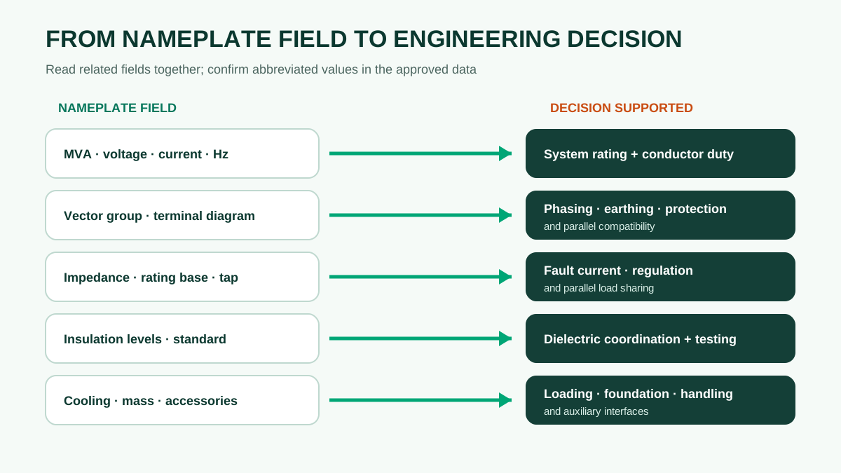
The connection symbol identifies winding connections, neutral availability and phase displacement. For example, Dyn11 describes a delta-connected high-voltage winding, a star-connected low-voltage winding with neutral brought out, and an IEC clock-number displacement. The symbol affects earthing, protection, harmonics and parallel-operation compatibility.
The terminal diagram shows which physical bushings correspond to each phase and neutral. Use it during installation and phasing checks; do not rely only on the sequence in which bushings appear on the tank.
Impedance and the stated reference
Short-circuit impedance influences fault current, voltage regulation and load sharing between parallel transformers. On multi-rating or multi-winding transformers, the plate or associated data may state more than one impedance value. Compare values only after confirming the MVA base, winding pair, tap position and reference temperature.
A small difference in presentation can change the engineering meaning. If the plate is abbreviated, the guaranteed technical particulars and test report should provide the full reference conditions.
Insulation levels and dielectric duty
Insulation markings can include lightning-impulse and power-frequency withstand levels for each winding and neutral. Interpret them under the governing IEC or IEEE specification rather than translating labels mechanically between standards. Check the highest voltage for equipment, system earthing, arrester coordination, altitude and any special switching-impulse requirement.
Temperature rise, insulation system and cooling code
The cooling code describes how the internal liquid and external cooling medium circulate. ONAN uses natural oil and natural air; ONAF adds forced air. The plate may also state temperature-rise limits or insulation-system information. These values belong to the approved thermal design and operating conditions; they are not a general permission to overload the transformer.
Masses, liquid and transport information
Oil-immersed power transformer plates commonly state total mass and may state insulating-liquid or active-part mass. These figures support foundation checks, lifting plans, oil handling and transport preparation. Compare them with the outline drawing and packing list. A shipping configuration with bushings, radiators or conservator removed will not have the same dimensions or mass distribution as the assembled unit.
Accessories and secondary ratings
Main transformer ratings do not describe every accessory. Bushing CT ratios and classes, cooling-motor supplies, control voltage, heater supply, alarm contacts and tap-changer motor data may appear on separate plates or drawings. The final document set should make these interfaces unambiguous for protection, control and site wiring.
| Nameplate field | Procurement or site decision | Document used to confirm it |
|---|---|---|
| Serial number and standard | Unit identity and applicable requirements | Final test report and data sheet |
| Rated MVA and cooling | Available load at each cooling stage | Guaranteed data and temperature-rise report |
| HV/LV voltage, frequency and taps | System compatibility and regulation range | Tap schedule and ratio test |
| Vector group and terminal diagram | Phasing, earthing, protection and paralleling | Approved connection drawing and vector-group test |
| Impedance | Fault level, regulation and load sharing | Guaranteed value and short-circuit impedance test |
| Insulation levels | Dielectric coordination | Specification and dielectric test reports |
| Total and liquid mass | Foundation, lifting, transport and oil handling | Outline drawing and packing list |
A five-step receiving check
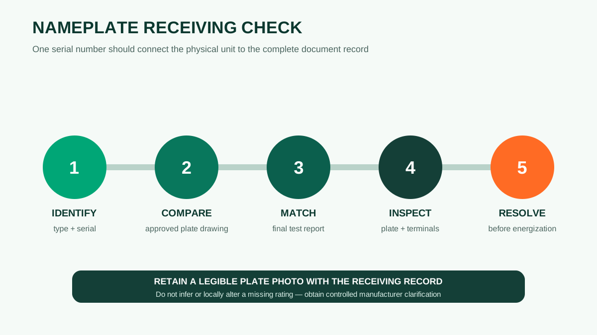
- Identify the unit: match manufacturer, type and serial number to the shipping documents.
- Compare the approved drawing: verify ratings, connection symbol, taps, cooling stages and masses.
- Match the test report: confirm the report belongs to the same serial number and that measured results refer to the stated rating.
- Inspect physical condition: ensure the plate is permanent, legible and consistent with terminal markings and fitted accessories.
- Record discrepancies before energization: do not correct a plate locally or infer a missing value; obtain a controlled manufacturer clarification.
What to include in an RFQ
An existing nameplate photograph is useful for a replacement or extension project, but it may not show the actual site duty. Send the single-line diagram, present loading, required future capacity, system voltage and frequency, short-circuit level, earthing method, ambient and altitude, applicable standard, installation constraints and any parallel-operation requirement. This allows the new offer to be checked against the system rather than copied blindly from an older unit.
Practical conclusion: the nameplate is a concise summary, not the complete specification. Read it with the approved drawings, guaranteed technical particulars and test report. When those documents disagree, resolve the discrepancy before shipment or energization.