
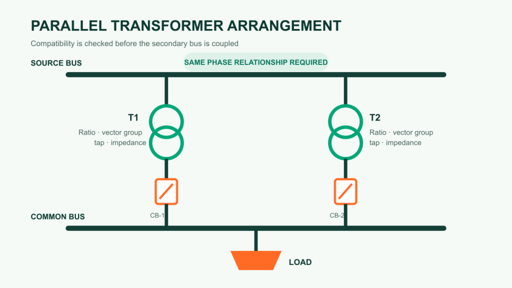
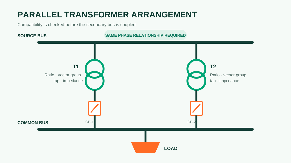
Transformers should be connected in parallel only after their voltage relationship, phase relationship and impedance characteristics have been checked as one coordinated system. Matching the nameplate kVA alone is not enough. A mismatch can create circulating current before useful load is supplied, force one unit to carry more than its intended share, or place incompatible secondary voltages on the same bus.
What parallel operation means
In a typical arrangement, two or more transformers are energized from a common primary system and their secondary terminals feed the same bus. The arrangement may improve maintainability, allow staged capacity or provide operational flexibility. It also makes the transformers electrically interdependent: a difference that is harmless when units operate separately can become important when their secondary terminals are tied together.
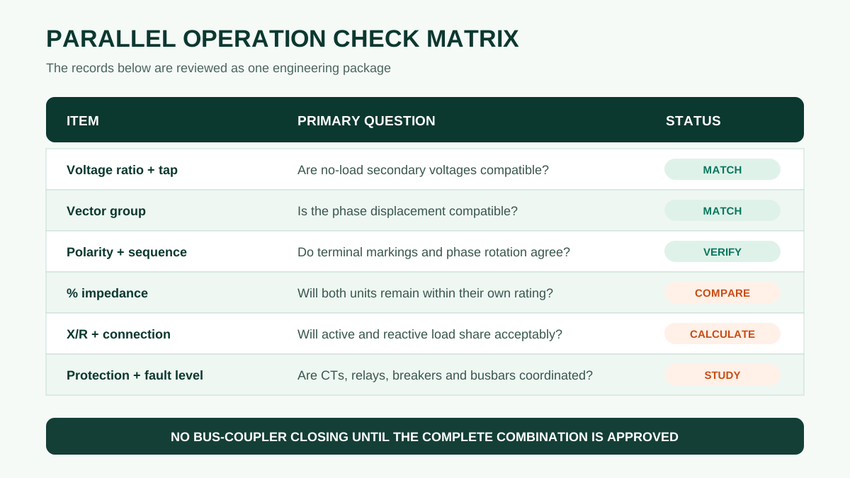
Six checks that must agree before paralleling
| Check | Why it matters | Evidence to review |
|---|---|---|
| Voltage ratio and selected tap | Unequal no-load secondary voltages drive circulating current between transformers even when the external load is small. | Guaranteed ratio, tap schedule, tap position and measured ratio results. |
| Vector group and phase displacement | Three-phase secondary voltages must have a compatible angular relationship. Different clock numbers cannot be assumed suitable. | Nameplate connection symbol, approved diagram and phase-displacement test. |
| Polarity and phase sequence | Incorrect terminal correspondence can create a severe fault when the buses are joined. | Terminal-marking drawing, phasing procedure and commissioning checks. |
| Percentage impedance | Units with different impedance values do not divide load in proportion to nameplate rating; the lower-impedance unit tends to take more load. | Guaranteed and tested short-circuit impedance on a common MVA and temperature basis. |
| Impedance angle or X/R ratio | Different impedance angles can cause unequal active and reactive load sharing and different power factors between units. | Design data or test information adequate for the system study. |
| System and connection impedance | Cables, bus ducts and switchgear between each transformer and the common bus also influence sharing. | Single-line diagram, conductor lengths and sizes, switchgear arrangement and short-circuit study. |
Rated power should also be reviewed. Transformers of different ratings can sometimes operate in parallel, but the percentage impedances and connection impedances must allow each unit to remain within its own thermal and current limits. The manufacturer or system designer should confirm the proposed combination rather than applying a universal size ratio.
Why ratio mismatch creates circulating current
When two secondary windings are connected to the same bus, their terminal voltages are forced toward a common value. If their no-load voltages differ because the ratios or tap positions differ, the voltage difference is applied across the combined transformer and connection impedance. Current can then circulate from one transformer into the other without serving the external load.
The result may be additional heating, unnecessary losses, abnormal reactive current or protection operation. For transformers equipped with on-load tap changers, the control philosophy matters as much as the static tap schedule. Independent controllers can move the units to different ratios unless they are designed and configured for parallel control.
How impedance affects load sharing
For a simplified comparison with equal voltage ratios and similar impedance angles, load share is approximately proportional to rated kVA divided by percentage impedance. This is a screening calculation, not a substitute for a system study.
Consider two 1,000 kVA transformers feeding a total load of 1,800 kVA. If Transformer A has 5% impedance and Transformer B has 6% impedance, the approximate shares are 982 kVA and 818 kVA respectively. Equal nameplate ratings therefore do not guarantee equal loading. If total load rises, Transformer A reaches its rating first.

Tap changers and parallel control
For de-energized tap changers, both units should be isolated and placed on the approved corresponding positions before parallel operation. The position number alone is not sufficient if the two tap schedules differ; compare the actual rated voltages for those positions.
For on-load tap-changing transformers, the scheme may use master-follower, circulating-current or other coordinated control. The selected method must suit the transformer impedances, voltage-regulation objective and network arrangement. Control-power supplies, position feedback, maximum current, line-drop compensation and loss of communication also need defined behavior.
Protection, earthing and switching checks
- Fault level: parallel sources can increase available short-circuit current. Confirm the interrupting and withstand ratings of switchgear, busbars and cables.
- Transformer protection: review differential zones, restricted earth fault, overcurrent grading, neutral protection and CT ratios for the parallel arrangement.
- Neutral and earthing: confirm how multiple neutrals are treated and whether zero-sequence current can divide through unexpected paths.
- Switching interlocks: define permissives and synchronization or dead-bus checks where required. Prevent an unapproved combination of incomers and bus couplers.
- Cooling capacity: each transformer must remain within the rating available for its operating cooling stage, not merely the combined station total.
Information to send for a parallel-operation review
- Single-line diagram showing sources, transformers, bus couplers, neutrals and earthing points
- Nameplate and guaranteed technical data for every transformer
- Rated power, voltages, frequency, vector group and complete tap schedules
- Guaranteed and tested impedance, including the rating and tap position used as the reference
- Existing test reports, terminal-marking drawings and protection diagrams
- Connection type, conductor size and approximate length from each transformer to the common bus
- Maximum and minimum load, power factor, motor starting and harmonic-producing loads
- System short-circuit level, switchgear ratings and proposed operating sequence
- OLTC control method and the required behavior during controller or communication failure
Practical conclusion: successful parallel operation is established by compatible secondary voltage phasors first, then by acceptable load sharing and a coordinated protection and control scheme. If any nameplate or test data are missing, keep the units on separate buses until the proposed combination has been reviewed.