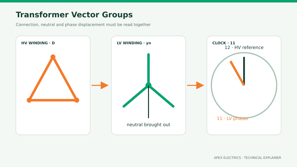
A transformer vector group describes three things at once: the winding connections, whether a neutral terminal is brought out, and the phase displacement between the high-voltage and low-voltage windings. It must be confirmed before protection design, cable phasing or parallel operation is finalized.
How to read an IEC vector group
IEC 60076-1 establishes the general basis for transformer connection symbols. Capital letters identify the higher-voltage winding and lowercase letters identify the lower-voltage winding. D or d means delta, Y or y means star, and Z or z means interconnected star (zigzag). N or n indicates that the neutral point is brought out to a terminal.
| Marking element | What it tells the buyer | Why it matters |
|---|---|---|
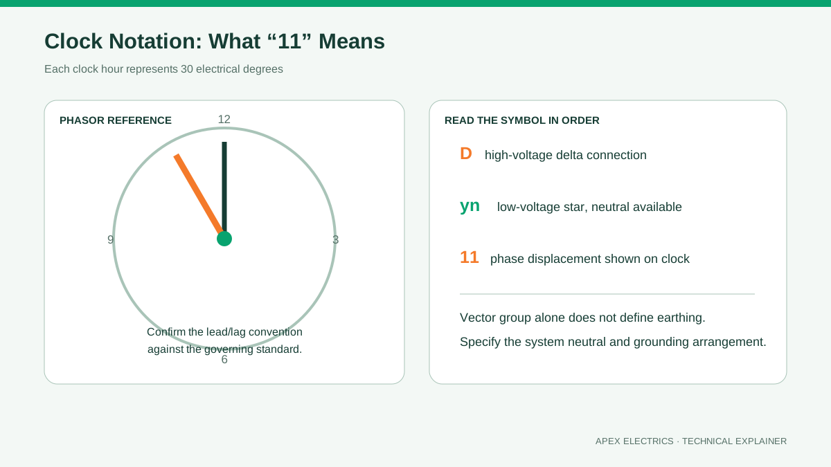
| D / d | Delta-connected winding | Influences zero-sequence current paths and harmonic behavior |
| Y / y | Star-connected winding | Provides a star point; the neutral is accessible only when N or n is stated |
| Z / z | Zigzag-connected winding | Used where a particular neutral or zero-sequence performance is required |
| 0–11 | Phase-displacement clock number | Critical for system phasing and parallel operation |
Why vector group selection is a system decision
No vector group is universally “best.” The correct choice depends on the network earthing method, required neutral, protection philosophy, harmonic environment, generator or converter interface and the connections of existing transformers. A distribution system that needs a four-wire low-voltage supply may require an accessible LV neutral. A project connecting to an existing bus must also match the site’s phasing convention.
The nameplate symbol alone is not a complete protection study. Earthing transformers, neutral grounding resistors, cable connections and relay logic can change how zero-sequence faults are detected and cleared. The approved single-line diagram should therefore be reviewed together with the vector group.
Can transformers with different vector groups operate in parallel?
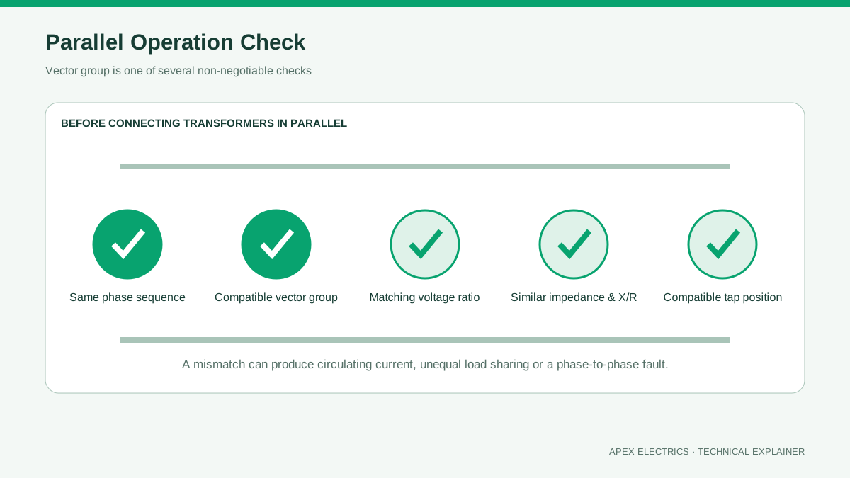
Usually not directly. Before closing two transformers onto the same bus, engineers must confirm compatible phase displacement and phase sequence, closely matched voltage ratios at the operating tap, compatible impedance and X/R ratio, and suitable rating and grounding arrangements. A phase mismatch can create severe circulating current even when the no-load secondary voltages appear similar.
What to state in a transformer enquiry
- Required vector group and the governing IEC or utility specification
- System nominal and highest voltages, frequency and phase sequence
- Whether the neutral terminal is required and how it will be grounded
- Existing transformer nameplate data if parallel operation is planned
- Protection scheme, converter loads and any unusual harmonic duty
- Approved single-line diagram and terminal marking convention
Common specification mistakes
A frequent mistake is copying Dyn11 from an earlier project without checking the grid interface. Another is writing “star secondary” but omitting whether the neutral must be brought out and rated for the intended duty. For retrofit work, relying on a product description instead of the existing transformer’s nameplate and factory drawings is also risky.
Practical conclusion: Select the vector group from the electrical system requirements, then confirm it on the single-line diagram, guaranteed technical particulars and nameplate drawing before production.