
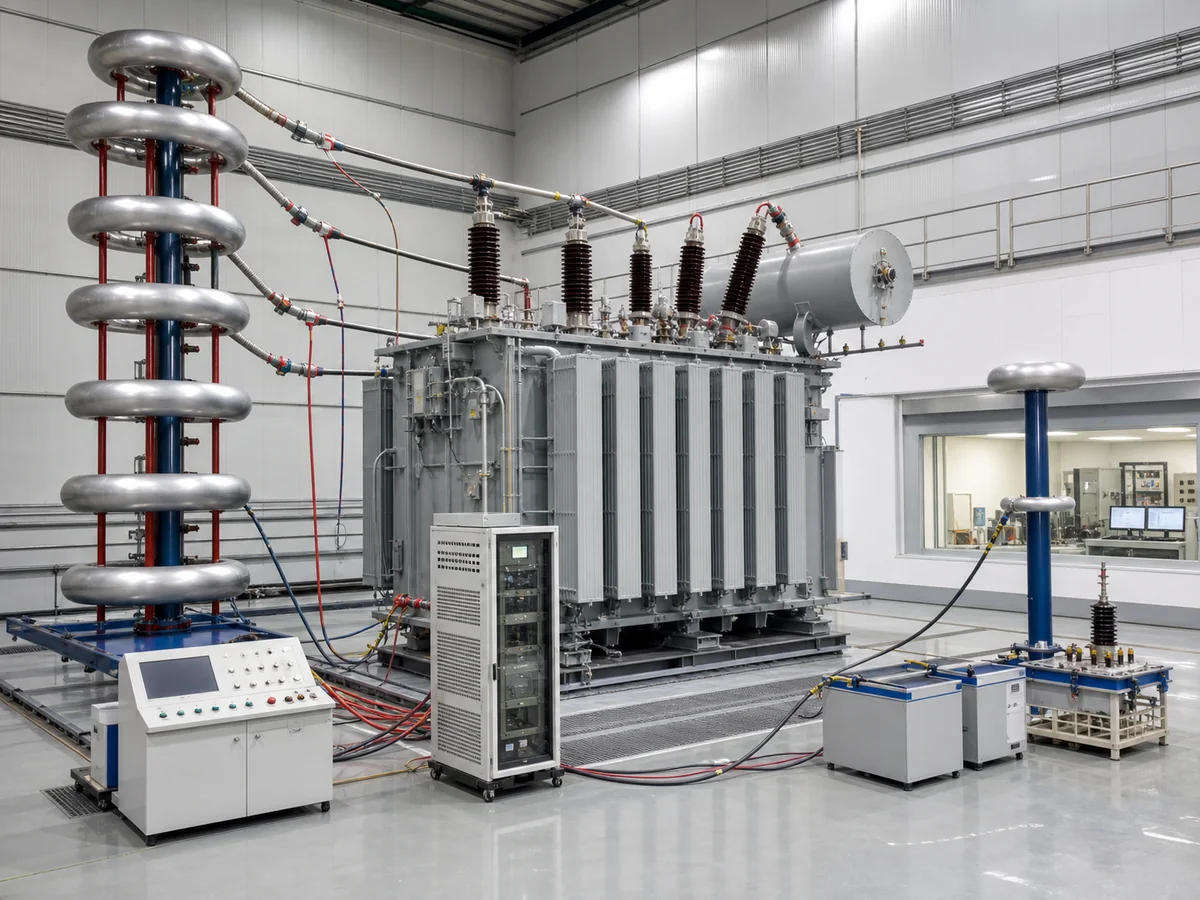
Factory tests verify that the completed transformer matches its design and agreed specification before shipment. A useful inspection plan does more than request “all standard tests”: it names the governing standard and edition, classifies each required test, defines witness points and states what records are needed for release.
Routine, type and special do not mean the same thing
| Test category | Purpose | Typical purchasing decision |
|---|---|---|
| Routine tests | Production checks normally performed on every completed transformer under the governing standard. | Confirm the exact list, acceptance criteria and whether the purchaser will witness or review records. |
| Type tests | Demonstrate a design characteristic or validate a representative design. | Decide whether an existing qualifying report is acceptable or a new test is required. |
| Special tests | Address project-specific performance, diagnostic or system requirements. | State the method, test condition, acceptance criterion, price and schedule impact. |
The exact classification and test list differ between IEC 60076, IEEE C57 and individual utility specifications. The contract should use the terminology of the selected governing document rather than mixing lists from different standards.
Core electrical checks on a completed transformer
Depending on transformer type and governing standard, the routine programme commonly addresses winding resistance, voltage ratio and phase displacement, no-load loss and current, load loss and impedance, insulation tests and the operation of accessories. These results answer connected questions:
- Do the windings and connections match the approved design?
- Are losses and impedance within the contractual basis?
- Is the phase relationship correct?
- Does the insulation withstand the required test stress?
- Do tap positions produce the intended ratios?
- Do protection, indication and cooling controls operate correctly?
Why measured values must be read together
A ratio result may look correct on its own, but the complete set of tap-position results can reveal a connection or labelling error. Measured load loss, resistance and test temperature must be consistent with the temperature-correction calculation. Impedance needs to be checked at the stated rating, frequency and tap position. The approved data sheet, nameplate, final drawings and test report should describe the same unit.
Examples of design-demonstration tests
Temperature-rise and lightning-impulse tests are common design-verification topics, but their classification and applicability must be taken from the governing standard and project specification. Large transformers may also require short-circuit withstand evidence based on design review, calculation or prior test experience unless a specific test is contractually required.
Never assume that a report for a transformer with the same MVA is automatically a valid type-test reference. Voltage class, winding arrangement, impedance, cooling and design family can affect relevance.
Special tests should answer a project question
| Project question | Possible test or study |
|---|---|
| Will sound meet the site limit? | Sound-level measurement using the agreed standard and operating condition |
| How will earth-fault current behave? | Zero-sequence impedance measurement where applicable |
| Is the insulation condition acceptable? | Agreed dielectric diagnostic measurements appropriate to the voltage class |
| Will inverter or rectifier duty add heating? | Harmonic-loss evaluation or specified measurement programme |
| Is tank tightness proven? | Leak, pressure or vacuum test as applicable to the construction and specification |
Build the inspection and test plan before manufacture
- List every required test.
Identify the standard clause, test method and agreed acceptance criterion.
- Set hold, witness and review points.
State which work cannot continue without approval, which tests may be witnessed and which records are reviewed after completion.
- Define notice and attendance.
Include notice period, remote-witness arrangements and what happens if a nominated witness does not attend.
- Approve the test procedure early.
Confirm circuit, instruments, correction methods, sequence and reporting format before the test bay is booked.
- Close deviations before release.
Record retests, concessions and outstanding documents in a controlled punch list.
What the final test dossier should contain
Key takeaway
Factory testing is most effective when it is planned as part of procurement, not added just before shipment. Select one governing standard, define the applicable test categories, identify witness points and require a final dossier that can be traced to the supplied transformer.
For quotation preparation, continue with How to Write a Power Transformer Specification or The Minimum Data Needed for a Reliable Transformer RFQ.