
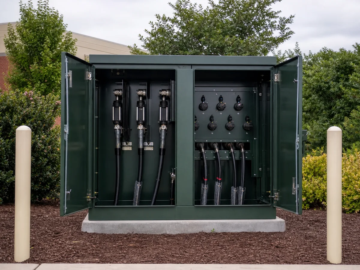
Two pad-mounted transformers with the same kVA and voltage can be physically incompatible. Before selecting a unit, establish how the utility feeds it, how crews operate it and which cables and separable connectors enter each compartment.
Answer these three questions first
Radial or loop?
This changes the number and arrangement of primary bushings and switching positions.
Dead-front or live-front?
Utility practice determines connectors, access and operating procedures.
Where is the fault cleared?
Coordinate bayonet fuses, current-limiting fuses, upstream devices and secondary protection.
Electrical data sheet
- Three-phase kVA and frequency
- Primary and secondary voltage
- Connection and vector group
- Impedance and tolerance
- BIL / insulation level
- Tap range and location
- Fluid and temperature rise
- Loss and sound guarantees
Draw the cable compartments
Specify bushing positions, parking stands, grounding pads, arresters, operating handles, metering space and cable openings. Then overlay actual cable size, bend radius and termination length. A dimensioned compartment drawing is more useful than “standard cable entry.”
Site conditions that change the enclosure
Public access, flood level, snow, wind, coastal atmosphere and expected corrosion category can affect the tank, doors, locks, sill, finish and foundation. Confirm working clearances and vehicle protection around the pad.
For North American-style three-phase pad-mounted units, utility requirements should be read together with standards such as IEEE C57.12.34; the utility’s construction standard may be more specific.