
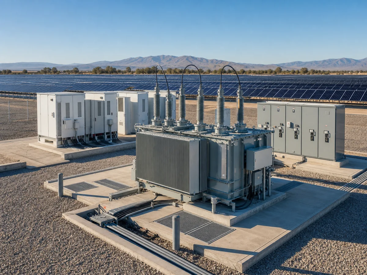
A solar step-up transformer does not see the same duty as a conventional constant industrial load. Output rises and falls every day, inverters may supply or absorb reactive power, and the transformer can remain energised when real-power production is low or zero.
Read the operating day, not only the nameplate
Energisation, auxiliary loads and rapidly changing inverter output.
Highest real-power loading, elevated ambient temperature and possible clipping.
Voltage ride-through, reactive current and protection coordination.
Possible energised no-load operation or reactive-power service.
Data required from the inverter supplier
- Operating voltage range
- Maximum continuous current
- Harmonic current spectrum
- Reactive capability curve
- Fault-current behaviour
- Overload and clipping strategy
- Grounding arrangement
- Switching sequence
These inputs influence winding voltage, MVA margin, thermal calculation, harmonic loss evaluation, shielding decisions and protection settings. “Suitable for solar” is not enough to define them.
Collector-block and main-transformer duties are different
A pad-mounted or skid transformer serves one or two inverter blocks and is repeated across the plant. The main step-up transformer sees the diversity of the whole collector system and grid-code requirements at the point of interconnection. Their loading cycles, redundancy and spares strategies should be considered separately.
Freeze interfaces before repeating the design
Approve one reference block covering inverter terminals, LV connection, transformer, MV switchgear, protection, communications, foundation and containment. Repetition then saves time. Repeating an unresolved interface only multiplies site modifications.