
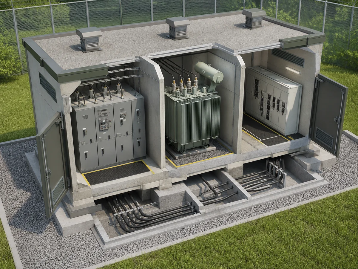
A compact substation combines medium-voltage equipment, a transformer and low-voltage distribution into a coordinated assembly. Its value is controlled interfaces and efficient site work, not the removal of spaces needed for cables, ventilation and people.
Design from the service route inward
- Place the equipment.Set vehicle access, lifting route, finished level and fire separation.
- Route the cables.Check trench position, bend radius, termination height, gland plates and segregation.
- Reserve operating space.Open every door, withdraw every device and model the safe switching position.
- Prove the heat path.Use transformer loss data and solar gain to size ventilation.
- Complete the civil interface.Freeze base channels, foundation openings, earthing, drainage and containment.
A small footprint can create a large maintenance problem
Ask how a damaged MV panel, LV breaker or transformer can be removed after the surrounding site is complete. If replacement requires dismantling the roof, blocking an escape path or cutting permanent buswork, the layout has transferred construction savings into future outage risk.
Common late discovery
The equipment fits in plan view, but the MV cable cannot make the required bend below the termination. Confirm cable geometry in section as well as plan.
Information needed before enclosure approval
| Electrical | Single line, ratings, fault level, protection and control supply. |
|---|---|
| Site | Ambient, altitude, pollution, wind, seismic duty, flood and fire strategy. |
| Operation | Access, switching sequence, internal-arc philosophy and egress. |
| Construction | Transport split, lifting, foundation, trenches, earthing and commissioning boundary. |