
Transformer inrush current is a transient magnetizing current produced when a transformer is energized. Its magnitude and waveform depend on the closing instant, residual core flux, transformer construction and the connected system. Because inrush can appear as differential current, protection must distinguish an expected switching event from an internal fault without relying on one universal current multiplier or harmonic threshold.
What creates transformer inrush current
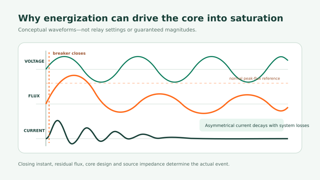
Under steady-state excitation, the applied voltage establishes an alternating core flux. When the breaker closes, the prospective flux begins from the core’s residual flux and from the instantaneous point on the voltage wave. An unfavorable combination can demand a transient flux above the normal operating peak. The core enters a saturated region, magnetizing inductance falls and a large, asymmetrical current flows until system losses reduce the offset.
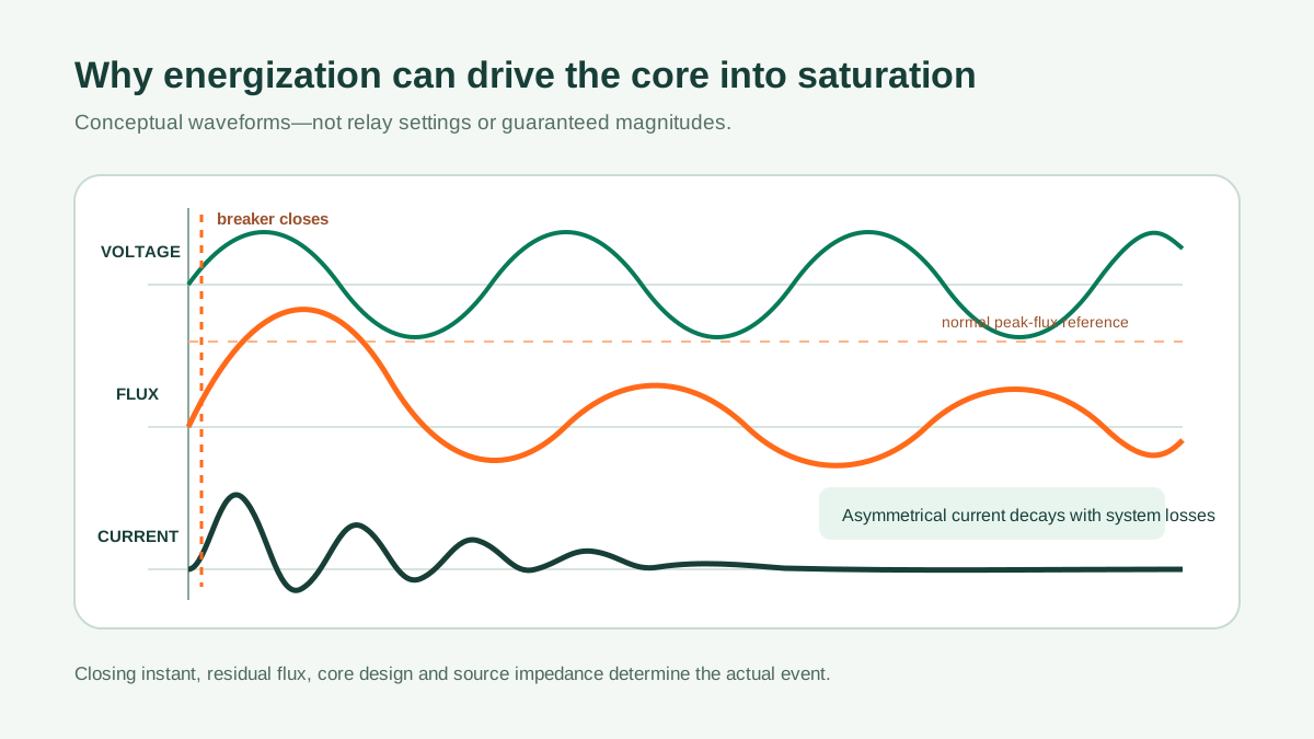
Factors that change the event include the energized winding, source strength and X/R ratio, core construction, remanent flux, breaker pole closing times, winding connection, parallel transformers and the impedance between the source and transformer. This is why a fixed statement such as “inrush is always a certain multiple of rated current” is not a reliable design rule.
Why current magnitude alone is not enough
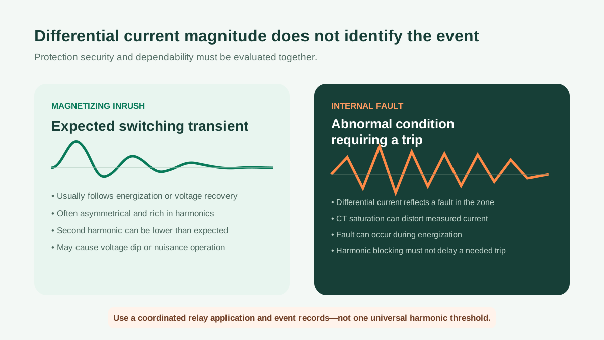
A transformer differential element compares currents entering and leaving its protection zone after ratio, phase-shift and zero-sequence compensation as applicable. During energization, current may enter from the source while little load current leaves, creating differential current even though the transformer is healthy. An internal winding or terminal fault also produces differential current, so the relay needs additional security logic.
| Evidence | Magnetizing inrush | Internal fault |
|---|---|---|
| Operating context | Usually associated with energization or voltage recovery | Can occur at any time, including during energization |
| Waveform | Frequently asymmetrical, with a decaying envelope and harmonic content | Depends on fault type, location, source and CT performance |
| Second harmonic | Often significant, but may be lower than a traditional expectation | May appear through waveform distortion or CT saturation |
| Required protection response | Remain secure unless another trip criterion is met | Trip rapidly and selectively |
| Best evidence after commissioning | Recorded first-close and subsequent energization waveforms | Relay event report, differential quantities, CT and breaker status |
How transformer differential protection handles inrush
Modern transformer relays can use percentage restraint, harmonic restraint or blocking, cross-phase logic, waveform recognition and unrestrained high-set elements in combinations defined by the relay design. Second-harmonic content remains an important indicator, but field experience shows that real inrush can contain less second harmonic than a traditional setting expects. Conversely, CT saturation during a severe fault can distort the waveform and produce harmonics.
The setting philosophy therefore has to balance two risks: an unwanted trip when a healthy transformer is energized, and delayed operation for an internal fault. The correct balance depends on the relay algorithm and the transformer/system application. Manufacturer defaults are a starting point for study, not a substitute for it.
When controlled switching or another mitigation is justified
For large or frequently switched transformers, the consequences of inrush may extend beyond the transformer differential relay. A weak source can experience a voltage dip; adjacent loads may be disturbed; mechanical and electrical switching duties can increase. An engineering study may consider controlled point-on-wave switching, closing resistors, a defined energization sequence or operating restrictions. Controlled switching uses the relationship between prospective and residual flux to select breaker closing instants, but it requires suitable equipment and application engineering.
Data required for an energization and protection study
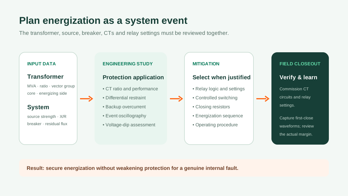
- Transformer MVA, winding voltages, vector group, impedance and core construction
- Which winding will be energized and whether other windings are open, loaded or connected to cables
- Source short-circuit strength, X/R ratio and network configuration for each operating case
- Expected residual-flux assumptions and breaker pole closing scatter
- CT ratios, classes, knee-point or transient-performance data and connected burden
- Relay manufacturer, model, firmware and proposed differential/restraint functions
- Parallel transformers, nearby motors, capacitor banks and sensitive loads
- Available oscillography and event records from comparable energizations
- Acceptable voltage-dip, switching and protection-performance criteria
What the equipment buyer should request
The transformer supplier should provide the final transformer data needed by the protection engineer, including vector group, guaranteed ratio and impedance, cooling ratings, CT data when CTs are in the supply scope, and relevant design information agreed for the study. The relay setting file and system protection approval normally remain the responsibility of the project protection authority unless that engineering service is explicitly included.
During commissioning, verify CT polarity and ratios, phase compensation, differential currents under stable conditions, breaker status logic and trip circuits. Capture the first energization waveform where the relay and commissioning procedure allow it. That record is valuable evidence for confirming security margin and refining future operating practice.
Practical conclusion: treat transformer energization as a system event. A reliable solution connects transformer design data, CT performance, relay algorithms, breaker behavior and network conditions—then confirms the result with commissioning records.