
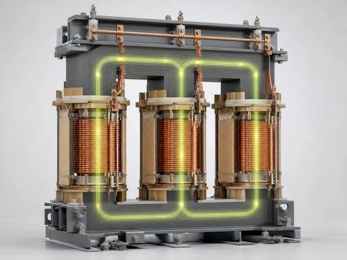
A transformer transfers alternating-current power between circuits through a changing magnetic field. It does not create energy, and its windings are normally not connected electrically to one another. The useful engineering questions are therefore not only “what voltage goes in and out?” but also “what establishes the magnetic flux, where do the losses occur, and what limits the usable rating?”
The working principle in four steps
- Alternating voltage is applied to the primary winding.
The applied voltage drives a magnetising current. This current establishes an alternating magnetic flux in the laminated steel core.
- The core provides a controlled magnetic path.
Most of the flux links both the primary and secondary windings. Laminations reduce circulating eddy currents inside the core material.
- The changing flux induces voltage in both windings.
Faraday’s law links induced voltage to the number of turns, operating frequency and rate of change of magnetic flux.
- A connected load draws secondary current.
The primary then draws additional current so that input power approximately balances output power plus transformer losses.
Turns ratio sets the ideal voltage ratio
Primary and secondary voltage are approximately proportional to their winding turns. The relationship is idealised; winding voltage drop and regulation affect the terminal voltage under load.
A step-up transformer has more turns on its high-voltage winding than on its low-voltage winding. A step-down transformer does the opposite. Frequency is not changed. If losses are temporarily ignored, apparent power on both sides is approximately equal, so current changes in the inverse direction:
A higher-voltage winding therefore carries lower current for the same transferred power, while insulation requirements become more demanding.
Why frequency and voltage must be considered together
Core flux is related to applied voltage divided by frequency and winding turns. Applying rated voltage at a lower-than-designed frequency increases flux density and can push the core toward saturation. Magnetising current, noise and heating may then rise sharply. This is why a 50 Hz and a 60 Hz duty cannot be treated as interchangeable by looking only at the voltage and kVA.
The transformer rating plate should be read as one coordinated set: voltage, frequency, phases, connection, cooling and rated power belong together.
What physically limits the transformer rating?
| Design area | Main duty | What must remain within limits |
|---|---|---|
| Core | Carries alternating magnetic flux | Flux density, no-load loss, exciting current and sound |
| Windings | Carry load current and withstand electrical forces | Temperature, voltage stress and short-circuit mechanical strength |
| Insulation | Separates turns, windings and earth | Power-frequency, impulse and long-term thermal stress |
| Cooling system | Moves heat from active parts to the environment | Oil and winding temperature rise, cooler duty and airflow |
| Tank and structure | Contains and supports the active parts | Pressure, vacuum where specified, transport and seismic loads |
Why terminal voltage changes under load
Real windings have resistance and leakage reactance. Load current passing through that impedance creates an internal voltage drop. The magnitude depends on current, power factor and transformer impedance. Tap changers adjust the effective turns ratio to keep system voltage within an acceptable range, but the required tapping method and range must match the network operating plan.
Three-phase connections do more than join windings
Star, delta and zigzag connections influence phase displacement, neutral availability, zero-sequence current and harmonic behaviour. The vector group communicates the connection and phase relationship. It must agree with system earthing, protection and any transformers intended to operate in parallel.
Information a buyer should provide
- Rated power and loading profile
- Primary and secondary voltage
- Frequency and number of phases
- Vector group and neutral arrangement
- System fault level and required impedance
- Insulation level and governing standard
- Ambient temperature and altitude
- Cooling method and installation environment
- Tap range and voltage-control method
- Loss, sound and monitoring requirements
Key takeaway
A transformer works because alternating current produces changing core flux and that flux induces voltage in another winding. Its usable performance, however, depends on a coordinated electromagnetic, thermal, dielectric and mechanical design. A reliable quotation therefore begins with the complete system duty—not capacity and voltage alone.
Review the available power transformer range, or send the project voltage, capacity, standard and installation conditions through the technical enquiry form.