
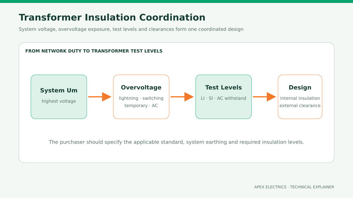
Transformer insulation level is selected from the overvoltages the equipment must withstand—not from nominal voltage alone. The decision starts with the highest voltage for equipment (Um), system earthing and insulation-coordination study, then assigns power-frequency, lightning-impulse and, where applicable, switching-impulse withstand levels.
From system voltage to transformer test levels
Nominal system voltage identifies the network, while Um defines the highest voltage class used for equipment insulation selection under IEC practice. The insulation-coordination study then considers lightning, switching and temporary overvoltages, surge-arrester characteristics, system earthing, incoming line exposure and the required margin. IEC 60076-3 specifies transformer insulation requirements, dielectric tests and external air clearances; IEC 60071 provides the wider insulation-coordination framework.
| Requirement | What it represents | Specification check |
|---|---|---|
| Applied / separate-source AC | Power-frequency withstand of insulation to earth | State the applicable terminal and duration from the governing standard |
| Induced AC | Interturn, phase-to-phase and related insulation stress | Confirm test voltage, frequency and enhancement level where required |
| LI / BIL | Lightning-impulse withstand capability | State full-wave level and any chopped-wave requirement |
| SI | Switching-impulse withstand at applicable higher voltage classes | Include only as required by the standard and insulation study |
| Neutral insulation | Withstand level at the neutral terminal | Define whether it is uniform or graded and how the neutral is grounded |
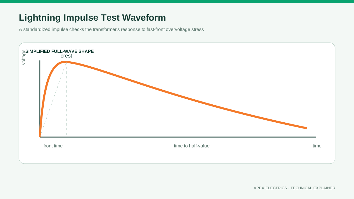
What the lightning-impulse test represents
A standard lightning impulse is a controlled high-voltage wave used to demonstrate insulation performance against fast transient stress. Its wave shape is defined by front time and time to half-value; the exact tolerances, test sequence and acceptance criteria come from the applicable standard. It is not a simulation of every possible field surge, and the selected level must work together with the surge-arrester protection scheme.
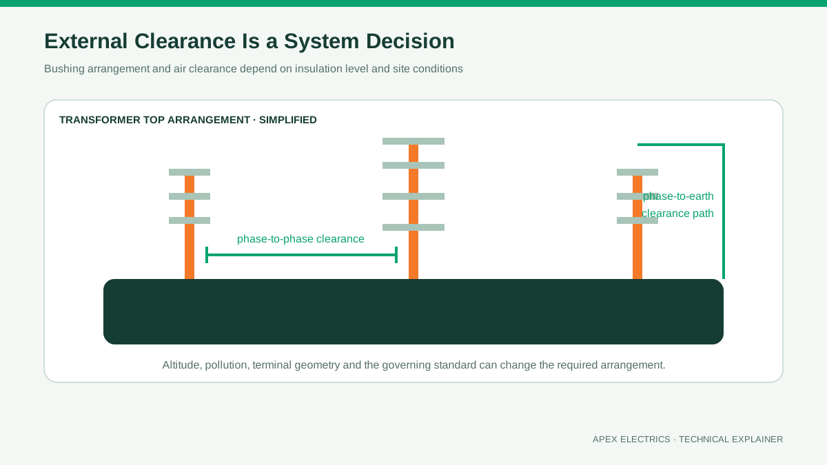
Altitude, pollution and clearances
External insulation is affected by installation altitude, air density, pollution severity, humidity and the geometry of bushings and clearances. Creepage distance along an insulating surface is not the same as clear air distance. A transformer specified only as “outdoor” may therefore be incomplete for a high-altitude, coastal, desert or heavily industrial location.
These external conditions do not justify an improvised change to internal insulation. The manufacturer should coordinate bushing selection, terminal clearances, surge protection and the transformer’s internal dielectric design as a complete system.
Information the purchaser should provide
- Nominal voltage, highest voltage for equipment and frequency
- IEC, IEEE/ANSI or utility insulation table to be applied
- System earthing and neutral connection
- Site altitude, pollution environment and indoor/outdoor installation
- Overhead-line or cable connection and surge-arrester arrangement
- Required LI/BIL, SI and power-frequency test levels for each terminal
- Any special test, chopped-wave or partial-discharge requirement
Practical conclusion: Do not choose BIL or LI from a generic online table alone. Confirm the equipment voltage class, project standard, earthing and overvoltage study, then place the agreed terminal-by-terminal levels in the transformer data sheet.