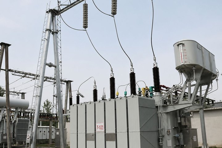
Utility and grid projects begin with a network problem, not a catalogue model. The equipment must match the system voltage, maximum fault level, neutral earthing, load forecast, reliability target and the utility’s own design practices. Apex coordinates the product definition and supply package around those inputs, then aligns drawings, test documentation, packing and delivery with the project programme.
Start with the network operating condition
A transformer rating alone does not describe how the unit will operate. The design review should identify normal and emergency loading, permitted voltage variation, expected future load, parallel operation and the consequence of an outage. These conditions influence transformer impedance, tapping arrangement, cooling stages, loss evaluation and monitoring.
| Project input | Why it matters | Typical equipment decision |
|---|---|---|
| System and highest equipment voltage | Establishes insulation coordination and terminal class | IEC or ANSI/IEEE voltage class, BIL or lightning impulse level |
| Short-circuit level | Determines electrical and mechanical withstand duty | Transformer impedance, switchgear rating and busbar withstand |
| Voltage regulation | Defines how secondary voltage must be maintained | Off-circuit taps or OLTC with automatic voltage control |
| Reliability philosophy | Sets acceptable outage and maintenance exposure | Single or duplicate transformers, bus sectionalising and spare strategy |
Equipment architecture
A grid connection may include a high-voltage power transformer, incoming and outgoing switchgear, protection and control panels, station service transformers, a DC system and MV or LV distribution. Smaller distribution projects may use oil-immersed transformers, compact substations or modular prefabricated rooms. The correct boundary depends on the owner’s single-line diagram and site responsibilities.
- Power transformers: project-engineered for voltage ratio, impedance, losses, cooling, tapping and transport.
- Distribution transformers: sealed or conservator units for utility feeders and local substations.
- Prefabricated substations: coordinated MV, transformer and LV equipment where factory integration reduces site interfaces.
- Switchgear: rated for the calculated continuous current, fault duty, protection philosophy and internal-arc requirement.
Protection, control and documentation
Protection must be coordinated across the transformer and connected switchgear. CT ratios, relay functions, trip interfaces, communication protocols and interlocking should be confirmed before drawings are approved. The document schedule normally covers data sheets, outline and foundation drawings, schematics, cable schedules, protection information, test reports, manuals and packing records.
Information for an initial review
Send the single-line diagram, system voltage and frequency, transformer capacity, primary and secondary fault levels, neutral earthing, load forecast, applicable standard, site conditions, destination and target delivery date. Where the network study is incomplete, Apex can identify the missing decisions so the quotation remains technically comparable.